In general terms, transduction refers to the conversion of energy from one form to another. In terms of piezoelectric transducers, it means the conversion of electrical to mechanical energy and/or vice-versa. This is made possible by the inclusion of active piezoceramic components in the transducer, and can take place in a variety of mediums (e.g., air, liquid, etc.) using a variety of transducer designs.
The piezo transducer’s ability to convert mechanical energy to electrical energy (and vice-versa) makes the generation and detection of sound waves possible. Transducers that generate audible-range sound waves can be used as speakers, buzzers, alarms, etc., while transducers that generate ultrasonic-range sound waves (above 20 KHz) can be used to measure distance in various mediums, determine flow rates in fluids, monitor fluid levels in vessels, atomize liquids, perform medical imaging, weld plastics or metals, monitor structural health, etc.
To simplify our discussion, we will break transducer design down into two main categories: single ceramic element transducers and multiple ceramic element (pre-stressed stack) transducers. Single-element transducers are often the most cost-effective option for signal generation and sensing applications, while multiple ceramic element transducers are best-suited for high power or large displacement applications. Both single- and multiple-element transducers rely on the piezoceramic component as the active element(s) for transduction.
Single-Element Transducers
Single-element transducers are often the most cost-effective solution, especially when experimenting with transduction for specific applications. By definition, single-element transducers contain one active ceramic element. This often results in a reduced cost and simplicity in design. They can be easily designed as transmitters, receivers, transceivers, etc. Applications for single-element transducers include medical, therapeutic, NDT (non-destructive testing), flow/level sensing, air transduction, distance measurement, fish finding, etc.
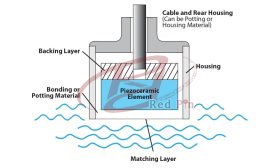
Single-element transducers are made up of four primary components, the piezoceramic element, the backing layer, the matching layer, and the housing/cable assembly (see Figure 1). Figure 2 shows two examples of single-element-style transducers that were custom built for various applications. It is easy to see the difference in the housing, the cable, and the matching layer materials, as well as the similarities in basic design.
Piezoceramic Element
In a single-element transducer, the ceramic element generates or receives the pulse and often operates at resonance. This simplifies the design and optimizes the performance. The ceramic element can also help determine the physical size of the transducer and its housing.
When choosing a ceramic element, start by thinking about what it is you are trying to accomplish. Whether transmitting, receiving, a simple pulse echo, or a complex crack detection, the application dictates the power requirements and beam angle, therefore setting the PZT material composition requirement (hard for high power applications vs. soft for low power and sensing applications) and physical size (physical size sets frequency and beam angle).
Housing
Once the ceramic element has been selected, the housing can be considered. The design of the housing is driven by the final application of the transducer and the size of the ceramic element required to meet the needs of the application. What are the size criteria, including the ceramic element size? How will it be mounted or integrated into a system? What might it be exposed to (e.g., environments, chemicals, gases, temperatures, etc.)? Are there regulatory requirements such as in the medical field? Will a portion of the housing also be utilized for electrical connections?
Common housing materials can be various types of aluminums, stainless steels, plastics, or other composite materials. Once a housing material and design is finalized, the process of selecting backing and matching layers can begin.
Matching Layer
The purpose of the matching layer is to provide a material “buffer” from the acoustic impedance of the ceramic element to the acoustic impedance of the medium through which the generated signal will be travelling. The acoustic impedance of a material is defined as the density of the material times the speed of sound through the material.
If the acoustic impedance mismatch is small enough, a single matching layer can be used. However, if the acoustic impedance mismatch is large, several matching layers may be required to work together to gradually transition from the impedance of the ceramic to the impedance of the target medium. Generally speaking, the higher the number of iterative steps in the matching layer and the closer the final match to the target medium, the higher the efficiency. Single matching layer efficiency can be in the range of 10-50%, while multiple layers can increase that efficiency by 25% or more.
Also important is the thickness of the material used for the matching layer. It is very common to use matching layers in ¼ wavelength increments to additionally enhance transmission efficiency and promote operation at resonance.
Backing Layer
In simple terms, the backing layer is a highly attenuative layer designed to direct energy out the front of the transducer and eliminate energy loss from the backside of the ceramic. The backing layer can be made of various materials, including air. Backing materials can also be used to control pulse resolution, at the expense of transducer efficiency.
When choosing a material for backing a transducer, it is important that the density be high for the purpose of acoustic impedance matching of the ceramic element, but the layer must also be attenuative. When backing with air, the thickness of the air layer is not critical. If backing with another material, however, the thickness will need to be determined by the material properties, density, and attenuation. A properly selected backing layer with high acoustic impedance can increase the transducer’s signal quality by absorbing and damping the back end signal from the ceramic element. If backing with air and potting the transducer, an air substitute must be used as a placeholder and is often made up of very specific foams or cork materials.
Cable Assembly
An often overlooked but critical part of the transducer, the cable assembly must be able to withstand the same environment as the transducer and have, in most cases, custom connectors to interface with the system for which it is being designed. It can be sealed through the housing, potted into the back of the transducer, have custom insulation, custom connectors, etc.
Example: Air Transducers
Standard air transducers are of the single-element style and operate at several “general” frequencies, the most common of which are 25, 40 and 300 kHz. The higher the frequency, the higher the measurement resolution (at the expense of measurement distance). Higher frequency air transducers are generally useful for high-resolution measurements at distances of 1.5-10 in., while some lower frequency units could measure fairly accurately at ~ 20 ft with adequate resolution.
When considering air transducers for a specific application, one may run across “transmitting” air transducers and “receiving” air transducers; they operate at slightly different frequencies to optimize efficiency. In a very basic sense, when measuring distance, level, or detecting objects, a “transmitting pulse” is generated and directed toward a target. The signal travels through air, is reflected off the target, and directed to the receiver. By measuring the time of flight of this “pulse” from transmitting to receiving, it is possible to determine distance, proximity, level, presence of an object, etc.
When transmitting, it is most common to operate the air transducer at its frequency of minimum impedance, or resonant frequency (Fr). Transmitting at this frequency generates the highest output signal for the input power applied and is therefore the most efficient driving condition. When using an air transducer in a receiving application, it is more efficient to receive signals at the frequency of maximum impedance, or anti-resonant frequency (Fa). This condition maximizes the signal generated by the transducer as the result of a mechanical stimulus, or incoming acoustic signal. The result is that 40-kHz air transducer transmitters operate at Fr = 40 kHz, while 40-kHz air transducer receivers operate at Fa = 40 kHz.
These optimized conditions are great if there is enough space for dedicated transmitting and receiving transducers, but this is often not the case. Therefore, air transducer “transceivers” are also fairly common. In a “transceiver” application, the air transducer’s Fa and Fr frequencies are centered around the desired operating frequency (in this case, 40 kHz; see Figure 3). Drive circuits and signal post-processing techniques can fill in the gaps, resulting in perfectly useful signals for many applications.
Multiple-Element Transducers
While single-element transducers are cost effective, useful for low power applications, operate at the ceramic element’s resonance, and are easy to drive and experiment with using basic equipment, multiple-element (or stack) transducers are generally custom designed for high power applications. In a multiple-element transducer, the entire transducer assembly becomes one mechanical system, with its own resonance, typically in the 20-100 kHz range. This means that the ceramic elements are generally not operating at resonance, but are acting as a driver to induce resonance in the entire mechanical system.
The multiple-element transducer is assembled primarily of five components, as seen in Figure 4. These components include a head mass, multiple ceramic elements, shims to provide electrical connections, a tail mass, and some way of assembling and pre-loading the stack (typically a bolt).
Head Mass
The head mass is the business end of the transducer. Ideally, a majority of the power generated by the transducer is directed through the head mass. This is achieved by using a material, generally metal (e.g., aluminum, titanium, etc.), which is lower in density and lower in acoustic impedance than the tail mass.
Tail Mass
In order for the transducer to operate as expected, the tail mass must be a material of higher density and higher acoustic impedance than the head mass so it can direct the generated energy forward, to the head mass, and ultimately into the system it is driving.
Ceramic Elements
The number, geometry, and arrangement of the ceramic elements helps define the transducer’s displacement, power output, and operating frequency (frequency is really a combination of mechanical system properties and ceramic element properties).
The orientation of the ceramic elements is critical, as the physical displacement of the ceramics should be maximized. To achieve this, it is common practice to arrange the elements mechanically in series (displacement is additive), but electrically in parallel (to keep driving requirements low). Traditionally, the ceramic elements would be driven in their radial mode inducing a diameter, and therefore also a thickness dimension change, thereby driving the mechanical system.
Shims
The shims provide an external electrical connection, as well as an interconnection for the ceramic elements. Typical shim materials include brass, copper, stainless steel or beryllium copper. They should be flat, hard, have high electrical conductivity, and provide a path for heat conduction (to help dissipate heat from the ceramics to the masses).
Bolt
It sounds simple, but the bolt is critical in the assembly of the transducer. The bolt must be made of a material with a relatively low coefficient of thermal expansion to prevent the loss of pre-stress while the transducer is operating and producing heat. Typically, these bolts would be torqued to about 30 lb*ft; with experience and standardization, the electrical output of the transducer during the pre-stressing process can be used to determine the final torque.
Additional Considerations
To complement these five basic components, the addition of a custom head mass, head mass assembly or amplification horn can tremendously increase and focus the transducer’s output. Applications for high-power transducers include ultrasonic welding for plastics and metals; ultrasonic cleaning for metal parts, automotive, ceramics, and industrial components; sonication and cavitation for increasing the kinetics of chemical reactions; other high-power medical applications, including ultrasonic scalpels and dental cleaners; and sonar.


 English
 日本语
日本语 中文
中文 русский